| AT
Keyboard Interface V1.04
[Toc]
[Top] |
AT keyboard interface with
RS232 link using PIC16F84
AT keyboard to RS232 interface for the personal
computer or RS232 compatible devices. This routine converts
AT keyboard scan patterns to ASCII characters and sends
them afterwards to the target device by using the RS232
transmission protocol. Support of english (QWERTY) and
modified swiss-german (QWERTZ) 'codepages'. There is no
visual interface at the terminal like a LCD display.
Unidirectional data flow: keyboard to RS232 target
device.
|
| AT
Keyboard Interface V2.04
[Toc]
[Top] |
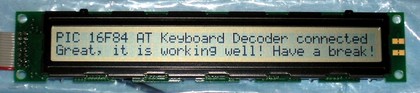
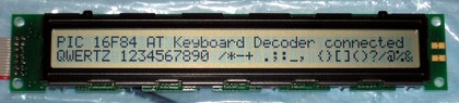
RS232 terminal with LCD
display using PIC16F84
AT keyboard to RS232 interface for the personal
computer or RS232 compatible devices. This routine converts
AT keyboard scan patterns to ASCII characters and transmits
them afterwards to the target device by using the RS232
transmission protocol. Support of english (QWERTY) and
modified swiss-german (QWERTZ) 'codepages'. This
implementation features a LCD display as visual interface,
but only for transmitted characters typed on the local
keyboard (unidirectional data flow). RS232 data
transmission is carried out using a software routine. No
reception of characters sent from RS232 target device,
because no RS232 modules with preemptive data reception
available yet.
|
| AT
Keyboard Interface V3.05 [Toc] [Top] |
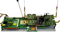
Fully operating RS232 terminal
with LCD display using PIC 16C74A
AT keyboard to RS232 interface for
the personal computer or RS232 compatible devices. This
routine converts AT keyboard scan patterns to ASCII
characters and transmits them afterwards to the target
device by using the RS232 transmission protocol. Support of
english (QWERTY) and modified swiss-german (QWERTZ)
'codepages'. This microcontroller application features a
dot matrix LCD display, and makes best use of the
microcontroller-internal USART, i.e. completely
hardware-based RS232 data transmission and reception.
Reception of external serial data is done using an
interrupt-based acquisition scheme. Visualization of
received data on the first line, user-entered data on the
second line of the dot matrix LCD display. This application
is best used with a 2 line by 20 or 40 characters LCD
display.
|
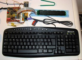
| AT
Keyboard Box V2.05 [Toc] [Top] |
Fully operating RS232 terminal
with LCD display and numeric foil-keypad using
PIC16F77
AT keyboard
to RS232 interface with completely bi-directional
communication capabilities. Multiple input devices are
attached, such as an AT keyboard and a small numeric
foil-keypad. The application features a dot matrix LCD
display to visualize the data received from the RS232
client on the first line, and the characters typed on the
locally attached keyboard on the second line. There is also
a piezo-beeper for acoustic feedback. This program converts
AT keyboard scan patterns to ASCII characters and transmits
them afterwards to the target device by using the RS232
transmission protocol. RS232 communication is carried out
by the microcontroller-internal USART, i.e. completely
hardware-based RS232 data transmission and reception.
Dynamic configuration of RS232 baud rate setting at
start-up (user-customization with 1200 baud -
115200 baud), with 12 seconds inactivity
time-out. In case the time-out applies, the
user-customization process terminates with the current
setting. Default setting after power-up is
9600 baud.
Support of english (QWERTY) and modified swiss-german
(QWERTZ) 'codepages'. This application is best used with a
2 line by 20 or 40 characters LCD display.
|
| AT
Keyboard Interface with Morse Code Support
V1.02 [Toc] [Top] |
AT keyboard interface with
RS232 link and Morse code PWM output using
PIC16F84
Technical
data as AT Keyboard Interface V1.03 above.
Additional pulse-width modulated (PWM) Morse code output.
Further parameterizable acoustic Morse code feedback
through Piezo beeper.
|
| AT
Keyboard Interface with Morse Code Support
V2.02 [Toc] [Top] |
AT keyboard interface with LCD
display, RS232 link and Morse code PWM output using
PIC16F84
Technical
data basically as AT Keyboard Interface V2.03 above
(except direct Ctrl-Hex and Alt-Dec entry). Additional
pulse-width modulated (PWM) Morse code output. Further
parameterizable acoustic Morse code feedback through Piezo
beeper. |