Design and Characterization of a
Strapdown Inertial Navigation System based on Low-Cost
Solid-State Sensors
Students project at the Electronics Laboratory of the Swiss
Federal Institute of Technology, Zurich, Switzerland
Students: Peter Luethi, Thomas Moser
Supervisor: Markus Uster
Design, Testing & Measurements: April 2000 - July 2000
Preface
Introduction
Aim of this Project
Mathematical Background
Coordinate
System
System Concept
System Outline
Components
System Architecture
Schematics
Measurements
Static
Spatial Representation Measurements
Dynamic
Spatial Representation Measurements
Static
Position Measurements
Dynamic
Position Measurements
Interpretation of Measurements
Orientation
Position
Enhancements to increase Accuracy
Initialization / Static
Calibration
Dynamic
Calibration
Conclusions & Outlook
References
Available Resources
Acknowledgements
The design of an inertial navigation system is a very complex
issue and requires profound skills in analog circuit design,
signal processing and algorithm programming. I have not the time
to answer all possible questions about this subject and to
provide support for any occuring problems.
Please refer first to the literature
references stated at the end of this page.
Inertial navigation is a well known concept deployed in aviation and space technology and other high technology areas. Inertial navigation systems (INS) are in general very expensive because of the demanding precision requirements, high computational efforts, and last but not least sufficient reliablity under harsh environmental conditions.
Inertial navigation is based on techniques, which have been invented and developed after the Second World War. The first systems were built of mechanical gyros, which required very complicated technical and power consuming constructions being prone to failure. Later on 'solid state' solutions have been realized by using only discrete integrated electro-mechanical or electro-optical sensors. These 'solid-state' systems had no moving parts (therefore Strapdown Inertial Navigation System), but consisted of expensive laser-based gyros and integrated sensor devices in MEMS technology (Micro Electro-Mechanical System).
Inertial navigation systems are used in civil and military
aviation, cruise missiles, submarines and space technology.
According to these areas of operation, the entire system and all
components have to be very precise and reliable. As a
consequence, the costs for such a system are still very high
(> 100'000 US-$) and they are rather big in
size.
 |
 |
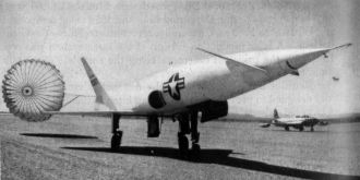
| Navaho test missile X-10 after completing first unmanned aircraft flight under control of inertial navigation guidance. The INS platform on the left is not a strap down type but rather is a conventional gimballed version. This results in a heavy and space consuming construction. (USA, September 1956) | |
Applications like mobile robotics, wearable computing, and
automotive electronics, ask for implementations which are both,
small in size and low in price. Industrial demand for low-cost
sensors in high volumes (car airbag systems, image stabilization
in video cameras) and recent progress in MEMS integration
technology have led to sensor products, which are now both small
(single chip solution) and inexpensive (~100 US-$).
With this thesis, it was not our goal to build a readily usable navigation platform. It was clear from the beginning, that this was not possible with these sensors. Instead we wanted to get hard data on what was possible with todays low-cost solid-state sensors. We wanted to characterize the performance achieved by our strapdown INS and to be able to estimate the required precision for an actual deployable platform.
Our task was to realize a portable strapdown inertial
navigation system based on low-cost acceleration sensors and
gyroscopes. Low cost in the context of this project means sensor
costs of up to 500 US-$.
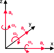
A body's actual spatial behavior / movement can be described with six parameters: for example with three translatory (x-, y-, z-acceleration) and three rotatory components (x-, y-, z-angular velocity). To be able to define the movement of the body, three acceleration sensors and three gyros have to be put together on a platform in such a way, that they form an orthogonal system. By integrating the individual translatory and rotatory components the current position and orientation can be calculated. Mathematic integration of the acceleration data yields the current speed, a second mathematic integration provides ultimately the distance travelled from the starting point. Since the angular sensors used within this project provide output data representing rotation speed (not angular acceleration), a single mathematic integration already yields the angular orientation. Performing these calculations accurately and periodically enables the ideal system to trace its movement with respect to a (virtual) reference point and to indicate its speed, current position and heading.
 |
.gif) .gif) |
| The six degrees of
freedom A body's actual spatial behavior / movement can be described with three translatory and three rotary components. |
|
The main limitation of the system performance is given with the finite precision of the sensors. A continuous small error in acceleration will be integrated once and results in a big error in actual speed, integrated a second time in a huge error in distance. Therefore very precise sensors and error correction mechanisms (feedback algorithms) are necessary to get an accurate inertial navigation platform. As an example, a 'cheap' feedback algorithm is the g-vector method. It does not require additional hardware, but simply assumes that the average direction of the z-acceleration vector points exactly rectangular down towards the earth surface and its average value is -9.81 m/sec². Another feedback method is the introduction of GPS position data fed to the INS, but this concept requires careful considerations about the update mechanism for not disturbing the entire system, especially in case you want to control devices and not simply measure their movements!
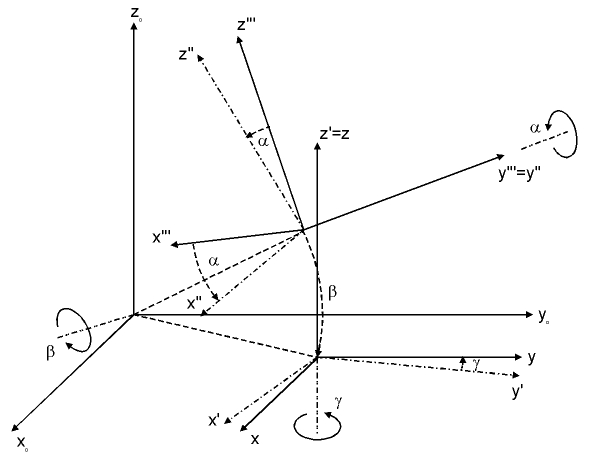
There exist several valuable choices of coordinate systems. The choose of the right system coordinates is a very important task, which needs careful evaluation! There exist different solutions: Some of them introduce redundancy to allow for improved precision in order to mitigate rounding errors. Some coordinate systems also have singularities, for example at the conventional earth coordinates with "North-" and "South-pole".
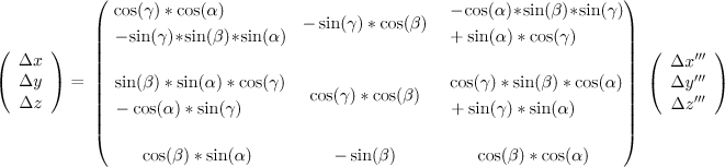
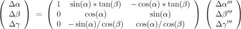
We have chosen the representation with 'Euler'-angles, even though it has singularities. It is, however, the most intuitive coordinate system and did not limit our measurements. It defines 3 axes: roll/bank (alpha), pitch (beta) and direction (gamma). There are always two coordinate systems: the initial system (x, y, z), usually where the unit was initialized, and the coordinate system of the unit itself (x''', y''', z'''). The three linear accelerations and the three angular speeds first have to be transformed into the initial system. Then they are integrated.
The translation to the components referring to the initial system proceeds as follows: (x"', y"', z"') =(alpha)=> (x", y", z") =(beta)=> (x', y', z') =(gamma)=> (x, y, z) .
|
Representation of the body's actual spatial situation (x"', y"', z"') referring to the initial system (x, y, z) by using 'Euler'-angles. |
|
Calculation of the actual acceleration (dx, dy, dz) referring to the initial system (x, y, z) and using the mathematic transformation based on 'Euler'-angles. |
|
Calculation of the actual angular velocity (dalpha, dbeta, dgamma) referring to the initial system (x, y, z) and using the mathematic transformation based on 'Euler'-angles. |
For further information please refer to the literature references at the end of this
page.
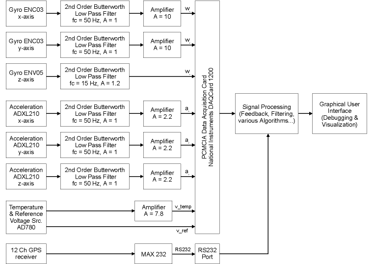
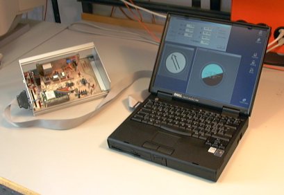
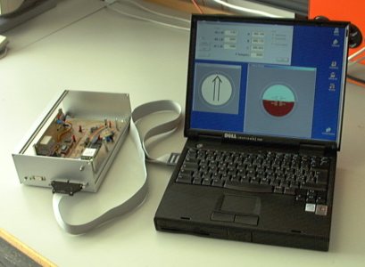
Since time was limited, we decided against developing our own processor board. Instead we bought a sufficiently performant PCMCIA DAQ (Data AQuisition) card, put the sensors on a separate board, and used a standard laptop as our host platform. This allows for quick software based changes on algorithms, convenient visualization and user interface, 'unlimited' processing resources and storage capacity:
Relying on this approach, we were able to focus entirely on
the realization of the low cost INS and its specific problems and
did not have to cope with other problems, such as limited
hardware (program memory) and processing (MIPS, FLOPS) resources,
finite precision (IEEE 754 floating point standard), all possible
hardware related problems (device programming), tools (IDE:
simulation, debugging), ...
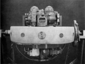
Gyro ENC03 as removable building block in a short 14 pin wide dual inline package. These devices are used for data acquisition in x- & y-axes. |
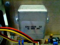
Gyro ENV05 vertically mounted to acquire data in the z-axis. This is a temperature compensated device. |
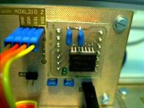
Acceleration sensor ADXL210 as removable building block in a short 14 pin wide dual inline package. Here only used for the z-axis. |
All sensor outputs are first led to second order Butterworth low pass filter stages to prevent aliasing and to reduce noise. These filters have a cutoff frequency of 50 Hz (except the filter for the precise gyro, which has only an output response frequency of 15 Hz) and are followed by an amplifier to perform optimum signal range adaptation at the analog inputs of the DAQCard1200. The A/D converter has different voltage input ranges, we decided to work in the 0 - 5V input range of the A/D converters.
The software features all necessary structures to fetch
acquired data and to calculate and display actual accelerations,
angular and translatorial speeds, and the current position. Since
my colleague and I are both familiar with airplanes and related
instrumentation, we implemented an artificial horizon and a
directional indicator (virtual compass). This 'instrumentation'
provided very valuable help during debugging of the entire INS,
and last but not least, served later on for convenient (and
impressive!) visualization of our achievements.
|
Data flow chart of our strapdown inertial
navigation system (INS) |
Data flow chart as PDF file: SystemFlow.pdf
(23 kB)
Software flow chart as PDF file: SW-Flow.pdf (2 kB)
|
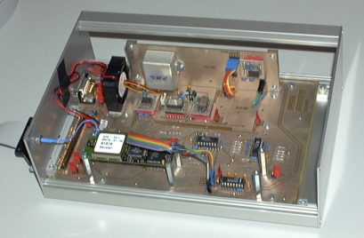
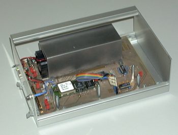
The final sensor board |
|
Experiments with the sensor board and mounted airflow channel (with small fan at the entrance on the left side) to get the ability for measuring a defined temperature uniform distributed over all sensors in order to compensate the inevitable temperature drift. But it is very important to keep the entire system at a place with minor temperature variations for not giving rise to dynamic temperature induced errors. |
|
The final setup: Strapdown Inertial Navigation
System |
| Sampling Rate | 150 Hz | 300 Hz | 500 Hz |
| Horizon after 30 sec | 2.5 deg | 2.0 deg | 2.0 deg |
| Direction after 30 sec | 0.7 deg | 0.5 deg | 0.5 deg |
| Horizon after 60 sec | 5.0 deg | 5.0 deg | 5.0 deg |
| Direction after 60 sec | 1.5 deg | 1.1 deg | 1.1 deg |
These measurements show the drift of our INS, not being moved in any direction, without any feedback or update mechanisms active. The horizon drift is larger than the directional drift, which can be explained by the cheaper and less accurate ADXL210 acceleration sensors. Another interesting thing to note: The drift after 60 seconds is about twice as large as the drift after 30 seconds. Thats because only one numeric integration occurs on these raw data, so error propagation is not as bad as with processing of raw acceleration data.
No adequate test equipment to make exact quantiative statements. It is important that the maximum angular velocity of the gyros is never exceeded (slowest device ENV05: +/- 80 deg/sec). Up to 30 degree swing, the resulting error is quite the same for all sampling frequencies. For larger swings, the magnitudes of error are dependent on the sampling frequency.
| Sampling Rate | 150 Hz | 300 Hz | 500 Hz |
| Deviation after 30 sec | 8 m | 8 m | 8 m |
| Deviation after 60 sec | 40 m | 40 m | 40 m |
Static position measurement means that the INS was not moved in any direction. We just measured the accumulated position error. The g-vector feedback mechanism was active. The drifts are quite large. Interesting to note that after 60 seconds the drift error is five times larger than after 30 seconds. The reason for this is the exponential error propagation caused by repeated numeric integration of noisy data without any sophisticated correction methods.
There has not been used any GPS data during all these measurements in order to get information about the achieved precision of our INS platform. It is obvious that in conjunction with additional GPS data, the characteristics of the entire system can be improved.
Useless at the moment. Does only make sense in conjunction
with additional GPS data, but then we will measure the GPS
accuracy and no longer the qualities of our INS platform.
The orientation measurement results look promising as such. Even though the sensors are very cheap, they yield a respectable result. The ENV05 internally uses the same sensor as the ENV03, but has provisions for temperature compensation. That's the reason why the directional drift is smaller.
The rotation sensors don't depend on the acceleration sensors. But with the help of them, errors can be corrected. Moving the sensor board around while applying combined error correction methods showed good results.
There were no reference measurements with the platform moving, because of the lack of a suitable infrastructure to do reproducible movements.
However, the results of the orientations measurements clearly are not good enough to support a platform for position indication. For more detail on that point, see next paragraph below.
The measurement results on position error show clearly, that the sensor accuracy is not nearly good enough for navigation. These are the static measurements. When moving the platform around, the position error was considerably bigger. This is also attributed to errors in the orientation: On earth there is a permanent acceleration of 1g, if the orientation horizontally is off by, say, one degree, we get a lateral acceleration error e1 of:
e1 = sin(1°) * g = 0.1712 m/s².
Integrating the acceleration error e1 twice, this results in an accumulated position error e2 after one minute of:
e2 = ½ * e1 * (60 s)² = 308 m !
So it is crucial for position measurement to have very
accurate orientation information! In our setup, these precision
requirements could not be met.
There exist several approaches to increase overall system performance:
The strapdown inertial navigation system as described before does not feature enough resources for standalone and accurate initial static calibration. The inherent problem is that we want to calibrate six independent components - three rotatory and three translatory. To carry out precise calibration of all these components, the following two preconditions have to be met:
These two preconditions provide data necessary to correct any deviations in sensor alignment and to calibrate the system according to the current sensor output values. Our INS platform relies on precise horizontal alignment, exact heading towards north, and a vertical g-vector of -9.81 m/sec² during initial calibration. In some applications such assumptions cannot be made, for example a ship will never be motionless enough. In such cases additional sensors must provide the necessary values.
Note, that the above horizontal static calibration activity is only targeting the zero values (DC offset) of the sensors. Any life-time induced alterations in sensor sensitivity can neither be detected nor corrected by this calibration procedure. On contrary, to be able to detect changes in acceleration sensitivity, it is required to place the INS box first in normal position, then x- and y-side up and down, and finally bottom-up. But this procedure only targets the acceleration sensors, the gyroscopes still remain for calibration.
Since the inevitable sensor errors result in unlimited growth of position and orientation errors, we tried to correct them also during operation with the introduction of adequate feedback mechanisms. In the following, we provide an enumeration of adequate feedback mechanisms applicable for dynamic calibration of inertial navigation systems. It can not be viewed as exhaustive.
| Feedback Mechanism | Description | Remarks |
| g-vector feedback | Concurrent calibration through calculation of magnitude and resulting direction of (average) acceleration vector (g-vector) | Assumption: The system is not used in a constantly accelerated environment, e.g. constant rotation. The system may need pauses to re-achieve its precision. |
| Electronic compass, earth magnet field |
Concurrent calibration of heading (direction updated/provided by z-axis gyroscope) | Might be disturbed by electromagnetic fields or metals. Compass might only operate in horizontal position. |
| Static GPS data (object not moving) | Concurrent calibration through calculation of actual position and speed (zero speed) | No GPS coverage in tunnels and cities with tall buildings |
| Dynamic GPS data (object moving) | Concurrent calibration through calculation of actual position, speed and heading (resulting direction of movement) | No GPS coverage in tunnels and cities with tall buildings |
| Speed information | All sorts of information from Doppler radar, wheel evolutions, air pressure,... |
| Component | Applicable Mechanisms for Dynamic Calibration |
| Acceleration, x-axis | g-vector feedback, static & dynamic GPS data |
| Acceleration, y-axis | g-vector feedback, static & dynamic GPS data |
| Acceleration, z-axis | g-vector feedback, static & dynamic GPS data |
| Angular velocity, x-axis | g-vector feedback, dynamic GPS data (if object is rotating or following a constantly bended path) |
| Angular velocity, y-axis | g-vector feedback, dynamic GPS data (if object is rotating or following a constantly bended path) |
| Angular velocity, z-axis | g-vector feedback, dynamic GPS data (if object is rotating or following a constantly bended path), electronic compass (only in horizontal position of object) |
An inertial navigation platform built of low cost sensors is
basically possible. Although the achieved precision is sufficient
for measuring the actual spatial representation (angles &
acceleration), further improvements have to be realized in
algorithms and hardware to get also sufficient accuracy for
position measurement. At the moment, getting accurate data of the
current position is impossible due to the limited precision of
the sensors. Our system needs at least an increase in sensor
precision of a factor of 10. We think that it is just a matter of
time until this requirement is met by the advance in both sensor
device engineering and manufacturing technology.
Corrections of systematic errors such as temperature drift,
non-linearities, and sensitivity deviations can lead to
significant improvements in overall system performance. With the
aid of adequate feedback mechanisms (g-vector, GPS position) and
signal processing algorithms (averaging, kalman filtering)
further improvements in precision can be achieved.
| C. F. Donnell et al., Inertial Navigation, Analysis and Design, McGraw-Hill, 1964 |
| D. H. Titterton and J. L. Weston, Strapdown Inertial Navigation Technology, Peter Peregrinus Ltd., 1997 |
| Anthony Lawrence, Modern Inertial Technology, Springer Verlag, 1993 |
| E. Nebot and H. Durrant-Whyte, Inertial Calibration and Alignment of an Inertial Navigation, in M2VIP'97, 1997, IEEE Press |
| E. Nebot, S. Sukkarieh, H. Durrant-Whyte, Inertial Navigation aided with GPS Information, in M2VIP'97, 1997, IEEE Press |
| Link: Considering buying an INS? Have a look at Xsens.com |
Our complete thesis report is available here, accompanied by the Visual Basic source code of the Cockpit application for inspirational purposes. While the original thesis report has been written in german, we eventually received an english translation: In 2008/2009, this thesis served as 'work of prior art' in a patent infringement case settled at the International Trade Commission in the United States.
| PDF report: | Low-Cost_INS_Report_DE.pdf
(7285 kB) Low-Cost_INS_Report_EN_Translation.pdf (315 kB) |
| Visual Basic 5.0 source code: | Cockpit.zip (38 kB) |
Special thanks to:
| My team member, Thomas Moser, who gave best efforts to cope with the software based problems. | |
| Matthias Nykos, Simon Maurer, Thomas Zwicker, Lukas Karrer, Pele and Bruno Wuethrich for joining our coffee breaks, and providing coffee powder, chocolate rabbits, and other ingredients. | |
| Electronics Laboratory of the Swiss Federal Institute of Technology, Zurich, Switzerland for the hardware support. |
Last updated: 2010/09/01